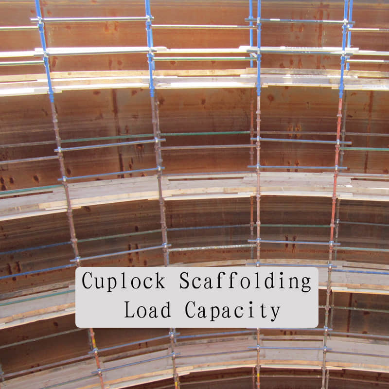
A Comprehensive Guide to Cuplock Scaffolding Load Capacity and Safe Working Loads
Nov 15, 2025
Precision is the name of the game in construction, especially when it comes to temporary structures such as scaffolding. Here, the margin for error approaches nil. Cuplock scaffolding has become a favourite the world over owing to the versatility of the system, speed of erection, and resilient construction, and it can be somewhere in used the scaffolding type for high-rise buildings, industrial jobs, and other constructions. However, the worth of any works must depend entirely upon one important factor: Knowledge of and compliance with the Cuplock scaffolding load limits. To disregard these loading limits is not merely breaking the regulations; it is inviting disaster upon those who are careless. In this comprehensive article, project managers, site engineers, and others who are involved in the purchase of scaffolding in their hands will find a comprehensive, practical article dealing with Cuplock systems, their rating, how the loads are computed, the necessity for conformity, and worker safety during all stages.
A Review Of The Cuplock Scaffolding System
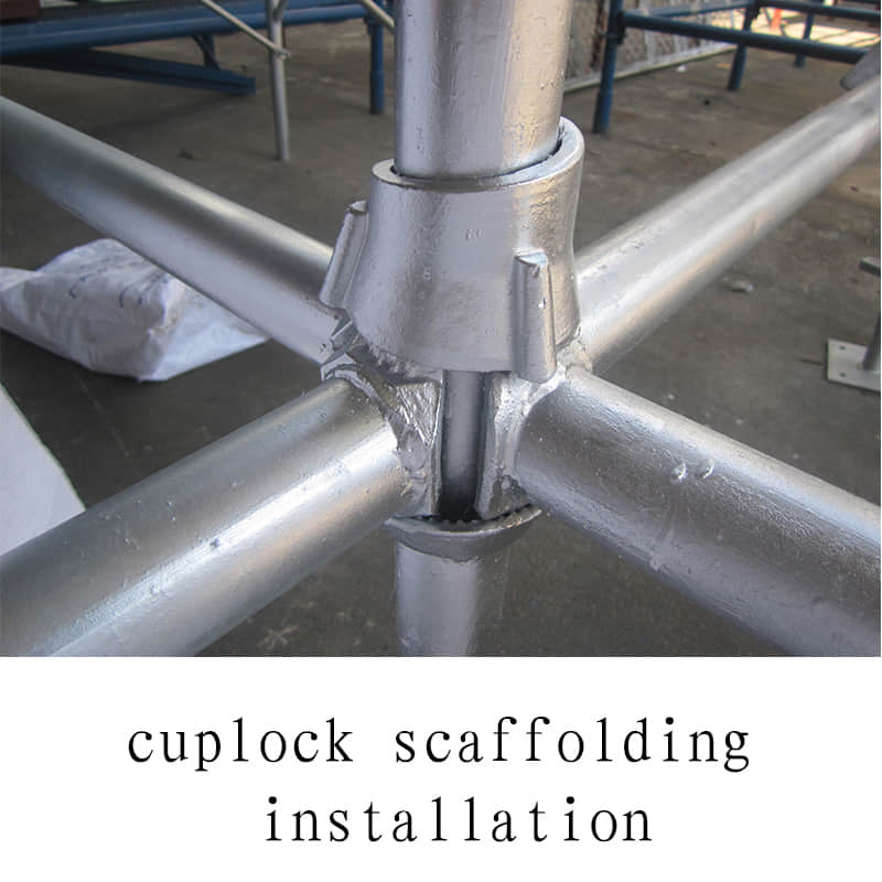
The Cuplock system is a modular-type scaffolding system that employs a special locking mechanism (the nodal system) that permits the attachment of up to 4 horizontal members (ledgers) to a vertical member (Vertical).
Key Components and Their Role in Load Bearing
Standards (Verticals): The primary load-bearing members. They transfer the entire weight of the structure, materials, and personnel down to the base plates.
Ledgers (Horizontals): They connect the standards and define the bay length. They also carry the weight of the working platforms and the distributed working load.
Top and Bottom Cups: The innovative feature. The bottom cup is welded to the standard, and the top cup locks the ledgers in place with a hammer blow, creating a rigid, load-sharing connection.
The load-bearing capacity of the scaffolding system is due to the rigidity and structurally imposed rigidity, which is built into the nodal Cuplock mechanism, in contrast to traditional tube and fitting scaffolding.
The Safe Working Loads (SWL)
All scaffolding materials have inherent limiting strengths, and the most significant term that you must be familiar with, under consideration of such materials, is the Safe Working Load (S.W.L.), or the Allowable Working Load.
What is SWL and Factor of Safety?
The SWL is the greatest weight that can safely be supported by the scaffolding system or particular part under normal working conditions. It is not the ultimate overwhelming load.
Engineering standards dictate that the SWL is determined using a Factor of Safety (FoS), which is typically 4:1 for scaffolding in many jurisdictions (e.g., OSHA, EN standards).
If, for example, a Cuplock standard is tested to destruction under a load of 40,000 Kg (40 tons), then its published safe working load will be 10,000 Kg (10 tons), which gives an enormous factor of safety against unforeseen stresses, material defects, or small erection mistakes.
B. How the Loads are Distinguished in Scaffolding Design.
In order to calculate the necessary load-carrying capacity carefully, engineers classify the possible weight under three headings:
Load Classification
Description
Calculation Focus
Dead Loads
The fixed, permanent weight of the scaffolding structure itself (Standards, ledgers, planks, couplers).
Component density and assembly configuration.
Live Loads
The non-permanent, movable weight of workers, tools, and stored materials on the platforms.
Usage class (Light, Medium, Heavy Duty).
Environmental Loads
External, dynamic forces such as wind pressure, snow load, or seismic activity.
Bracing, tie-ins, and geographical location.
Cuplock Scaffolding Load Capacity: By Application
The load capacity is not a single, fixed number; it is dependent on the intended use of the working platform, which determines the required SWL per square meter.
Load Classes According to Industry Standards (e.g., EN 12811)
Scaffolding Class
Usage Example
Minimum Permissible Uniformly Distributed Load (UDL) (kg/m²)
Class 1 (Light Duty)
Inspection, access only.
0.75 kg/m²
Class 2 (Light Duty)
Painting, cleaning, and light repairs.
1.50 kg/m²
Class 3 (Medium Duty)
General construction, plastering, rendering.
2.00 kg/m²
Class 4 (Heavy Duty)
Bricklaying, stone masonry, and heavy material storage.
3.00 kg/m²
Class 5 (Special Heavy Duty)
Exceptionally heavy work, specialized equipment.
4.50 kg/m²
Project managers must specify the correct load class during the design phase to ensure the correct standard gauge and bracing are used.
Crucial Role of the Standard (Vertical) Capacity
The primary determinant of the overall structural capacity lies in the ability of the standards to withstand axial compression.
Typical Cuplock Standard Capacity (Example): Depending on the steel grade, wall thickness, and effective length (distance between cups), a typical Cuplock standard can often support an axial load of up to 60 kN (approx. 6,000 kg or 6 tonnes) before buckling is considered. This figure is an illustration; always consult the manufacturer's specific technical data.
The total weight on any single standard (calculated by dividing the total expected load in a bay by the number of standards in that bay) must never exceed this certified SWL.
Safety and Compliance Optimization Best Practices
Obtaining rated load capacity is not merely a result of having high-quality components; it also requires scrupulous planning and execution.
1. Rigorous Foundation and Base Plate Checks
The load-bearing capacity of the total system is determined by its weakest link. Make sure the ground is level and compacted, and that it can support the high point loads transferred by the base plates used. Use sole boards or sills to properly distribute the load over a larger area.
2. Correct Bracing and Tie-Ins
Bracing is necessary for lateral stability and the transfer of environmental loads. Facade bracing (diagonal bracing) must be done in accordance with the design to prevent the standards from buckling. Tie-ins, non-negotiable in providing stability against wind loads, tie the scaffold into the permanent structure.
3. Adherence to Bay Sizes
Standard bay sizes (e.g., $2.5m \times 1.2m$) are certified for specific loads. Altering these dimensions without re-engineering the scaffold will dramatically reduce the load capacity and invalidate safety certifications.
4. Material Storage Protocols
Never exceed the specified platform load. Establish strict site protocols for material placement. Materials should be loaded directly above the standards wherever possible, minimizing eccentric loading on ledgers.
Conclusion
Understanding the Cuplock scaffolding load capacity is the cornerstone of responsible construction practice. It moves beyond mere component specifications into a holistic understanding of structural engineering, risk mitigation, and regulatory compliance. For architectural and engineering firms, this knowledge ensures project design integrity. For scaffolding rental companies, it guarantees asset longevity and minimizes legal exposure.
By committing to certified components, rigorous assembly procedures, and strict adherence to SWL protocols, you ensure not only the safety of your workforce but the success and reputation of your entire project.
Is your next project demanding a specialized load configuration?
Don't compromise on safety or compliance. Partner with [AJ Scaffolding] for certified, expertly maintained Cuplock scaffolding systems and professional design consultation.
Contact our certified engineers today to discuss your project's precise load-bearing requirements and ensure a compliant scaffold design.
FAQ
Does the height of the scaffold reduce its load capacity?
Yes. Taller scaffolds are more susceptible to column buckling. They require stringent bracing and regular ties to maintain the designed SWL and stability.
What is the biggest site risk that compromises Cuplock load capacity?
Inadequate Bracing and Poor Foundations (uneven ground or insufficient sole plates) are the two primary causes of capacity failure.
Can Cuplock be used for heavy concrete shoring?
Yes, but only when configured as Special Duty with dramatically reduced bay sizes and maximum cross-bracing to handle the high, concentrated vertical loads.


 en
en fr
fr es
es